PFA BUILD No 181-12742
VANS BUILD No 23578
Constructed 1996/7
Builder Roger Hopkinson
ISSUE: 3.6 30-Jun-03
|
RV-6A SPECIFICATIONS
|
|||
|
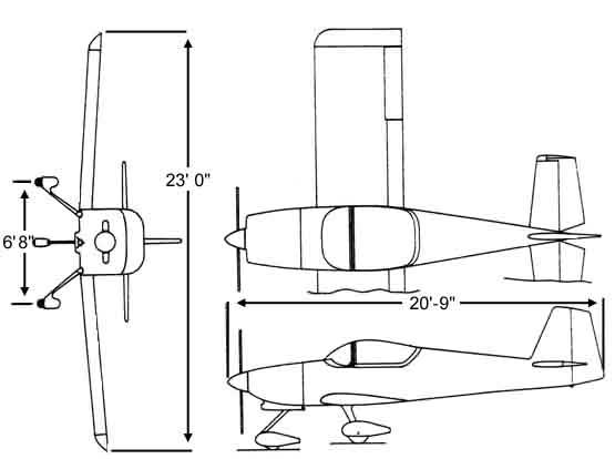
Span |
23’0" |
Wing Loading (lbs/sq.ft) |
15 |
|
Length |
19’9" |
Power Loading (lbs.hp) |
10.3 (160 hp) |
|
Height |
6’8" |
Engine(hp) |
150-180 |
|
Wing Area (sq. ft) |
110 |
Propeller |
Wood fixed pitch |
|
Empty Weight (lbs) |
985 |
Fuel Capacity (US gallons) |
38 |
|
Gross Weight (lbs) |
1650 |
Baggage |
60 |
|
RV-6A Solo Weight (1240 lbs) |
RV-6A Gross Weight (1650 lbs) |
||||||||
|
Engine (hp) |
150 |
160 |
180 |
Engine (hp) |
150 |
160 |
180 |
||
|
Top Speed |
196 |
200 |
208 |
Top Speed |
195 |
199 |
207 |
||
|
Cruise (75% 8000’) |
185 |
189 |
197 |
Cruise (75% 8000’) |
184 |
188 |
196 |
||
|
Cruise(55% 8000’) |
167 |
170 |
177 |
Cruise(55% 8000’) |
166 |
169 |
176 |
||
|
Stall Speed |
49 |
49 |
49 |
Stall Speed |
55 |
55 |
55 |
||
|
Takeoff Distance(ft) |
325 |
300 |
270 |
Takeoff Distance (ft) |
560 |
535 |
485 |
||
|
Landing Distance(ft) |
300 |
300 |
300 |
Landing Distance(ft) |
500 |
500 |
500 |
||
|
Rate of Climb(fpm) |
1665 |
1850 |
2225 |
Rate of Climb(fpm) |
1305 |
1450 |
1740 |
||
|
Ceiling(ft) |
18.500 |
20.500 |
24.700 |
Ceiling(ft) |
14,750 |
16,300 |
19,700 |
||
|
Speed Ratio |
4.:1 |
4.12:1 |
4.25:1 |
Range(75% 8000’) statute miles |
760 |
760 |
705 |
||
|
Range(55% 8000’) statute miles |
875 |
875 |
810 |
||||||
SECTION
APPENDICIES
SECTION 1
This Pilot’s operating handbook is designed as an appropriate information manual and to provide information relevant to achieve maximum utilisation of the Aircraft. It is not designed to be a substitute for adequate and competent flying instruction and should not be used for operational purposes unless kept up to date.
Assurance that the Aircraft is airworthy is the responsibility of the owner. The Pilot in command is responsible for ensuring the Aircraft is safe for flight and for operating within the limits detailed in this handbook and as displayed on placards and instrument markings in the Aircraft and in accordance with a current Permit to Fly issued by the Popular Flying Association.
Engine Manufacturer Lycoming
Model Number B 2 B
Rated Horsepower 160
Rated Speed (rpm) 2700
Displacement (Cubic ins) 320
Compression Ratio 8.50:1
Type Four cylinder, Direct Drive
Horizontally Opposed, Air Cooled
Manufacturer MT-propeller
Model MTV-18-C180-119
Number of blades 3
Diameter 71 ins
Type Electrically controlled
Variable pitch (manual) or Constant Speed (auto)
Limitation 2700 rpm
1.4 FUEL
Capacity 38 Gal (US) 31.6 Gal (imp)
144 Litres
Useable Fuel (Gal and Litres) To be established
Fuel Grade, Aviation 100/130 Green
Oil Capacity 8 US qts 7.6 Litres
Specification Ref Lycoming Manual
Viscosity to Ambient Temp for starting:- SINGLE MULTI - GRADE
Above 60 F SAE 50 SAE 40 or 50
30 F to 90F SAE 40 SAE 40
0 F to 70 F SAE 30 SAE 40 or
20W-30
Below 10 F SAE 20 SAE 20W-30
Maximum take off/landing weight 1650 lbs
Max Baggage Weight 100 lbs (subject
to Weight & Balance)
Standard empty weight 1131 lbs (Incl full
oil)
Maximum Useful load 519 lbs (Subject to weight & Balance)
Wing loading 14.5 lbs per sq ft
Power loading 10 lbs per hp
1.9.1 General Airspeed Terminology
CAS Calibrated air speed. Indicated airspeed
corrected for position and instrument error. Equates to true airspeed
in standard atmosphere at sea level.
KCAS CAS in"Knots"
GS Ground speed. Speed relative to the ground
IAS Indicated Airspeed. Speed shown on Airspeed Indicator
assuming no instrument error.
KIAS IAS in "Knots"
TAS True airspeed relative to undisturbed air which is
the CAS corrected for altitude, temperature and pressure.
Va Manoeuvring speed. Speed at which full application
of aerodynamic control will not over stress the aircraft
Vfe Maximum Flap Extension Speed. Highest Speed permissible
with wing flaps in a prescribed extended position.
Vne Never exceed speed. Not to be exceeded at any time.
Vno Maximum Structural Cruising Speed. Not to be exceeded
except in smooth air and then only with caution.
Vs Stalling Speed. The minimum steady flight speed at
which the Aircraft is controllable.
Vso Stalling Speed. The minimum steady speed at which
the Aircraft is controllable in the landing configuration.
Vx Best Angle of Climb. Airspeed that delivers greatest
altitude gain in shortest horizontal movement.
Vy Best Rate of Climb. Airspeed delivering greatest altitude
gain in shortest possible time.
1.09.2 Meteorological Terminology
ISA International Standard Atmosphere. Air is dry perfect gas. 15 deg C (59 deg F) at sea level. Pressure at sea level 1013 mb (29.92 in hg.)
OAT Outside Air Temperature. Free static air temperature. Obtained from meteorological sources or in-flight instruments adjusted for instrument error.
Indicated Pressure Altitude Number read from altimeter barometric sub-scale when set to 1013 mb.
Pressure Altitude Altitude measured from standard sea level pressure 1013 mb by a pressure or barometric altimeter. The indicated altitude corrected for position and instrument error (assumed zero error in this book).
1.09.03 Power Terminology
Take off Power Maximum power permissible for take off
Maximum Continuous power. Maximum power permissible continuously during flight.
Maximum Climb power Maximum power permissible during climb
Maximum Cruise power Maximum power permissible during cruise.
1.09.4 Aircraft Performance Terminology
Climb Gradient Demonstrated ratio of the change in height during a climb to horizontal distance covered in a given time.
Demonstrated Crosswind Velocity. Demonstrated crosswind component for which adequate control of the aircraft during take off and landing has been demonstrated (during certification)
Accelerate-Stop Distance Distance to accelerate to a specified speed and, assuming engine failure when that speed is attained, bring the aircraft to a stop.
1.09.5 Weight and Balance Terminology
Reference Datum Imaginary vertical plane from which all horizontal distances are measured for balance purposes.
Station Location along fuselage given in terms of distance from Reference Datum.
Arm Horizontal distance from reference datum to the centre of gravity of an item.
Moment Product of weight of an item multiplied by its arm.
Centre of Gravity (CG) Balance point of aircraft if suspended.
CG Arm Arm obtained by adding the aircraft individual moments and dividing the sum by the total weight.
CG Limits Extreme CG locations within which the aircraft must be operated at a given weight.
Usable fuel Fuel available for flight planning
Unusable fuel Fuel remaining after a run out test.
Standard empty weight Weight of aeroplane including usable fuel, full operating fluids and full oil.
Basic Empty Weight Standard empty weight plus optional equipment.
Payload Weight of occupants, cargo and baggage
Useful Load Difference between take off weight and basic empty weight.
Max Take off weight Maximum weight approved for start of the take off run
Max Landing Weight Maximum weight approved for the landing touchdown.
Max Zero Fuel Weight Maximum weight exclusive of usable fuel.
1.09.06 Useful Conversion Factors
| Multiply | By | To OBTAIN |
| Gallons Imperial |
1.201 4.546 |
US Gal Litres |
| US Gall |
0.83268 3.7854 |
Gal (imperial) Litres |
| Litres |
0.264172 0.2200 |
US Gal Gal (imperial) |
| Knots (Kt) |
1.1516 1.852 |
Statute Miles Km |
| Pounds (lbs) | 0.453592 | Kg |
DENSITIES
Fuel 7.2 lbs per Imp Gal or 1.58 lbs
per litre
Oil 9.0 lbs per Imp Gal or 1.98 lbs per litre
SECTION 2
LIMITATIONS
2.01 Airspeed Limitations
INDICATED AIR SPEED
Vne Never exceed 212 mph 184
kts
Vno Normal operations, smooth air 180 mph 156 kts
Va Do not make full or abrupt control 135 mph 115 kts movements
above. (blue line)
Full elevator would generate 6G
Vfe Flap extension speed:
20 deg flap 110 mph 96 kts
40 deg (full) flap 100 mph 87 kts
NOTE: Because of high ratio of top speed to stall speed and Manoeuvring speed the Aircraft is more susceptible to pilot induced over-stress than most other contemporary aerobatic aeroplanes. THE PILOT CAN THEREFORE EASILY IMPOSE DESTRUCTIVE LOADS ON THE AIRFRAME ABOVE THE RELATIVELY LOW MANOEUVRING SPEED. NOTE LIMITATIONS, EXERT CAUTION AND FLY ACCORDINGLY.
2.02 Airspeed indicator Markings
MARKING AND INDICATED AIR SPEED
Red line (Never exceed) 212 mph 184
kts
Blue Line (Manoeuvring speed max) 135 mph 115 kts
Yellow (Caution - smooth air or light turbulence) 180/210 mph 155/180
kts
Top Green Arc (max structural cruise) 180 mph 155 kts
Bottom Green Arc (Flap-less stall) 55 mph 48 kts
Top White Arc (max speed full flap) 100 mph 87 kts
Bottom White Arc (Stall full flap) 50 mph 44 kts
2.03 Power plant limitations
Based on installed engine Lycoming B2B 0 320 (modified sump and internal oil feed to reposition Carburettor)
Maximum horse power 160
Max speed 2700 rpm
Oil temperature:- Maximum 245 Deg.F Desired 180
Deg.F
Oil pressure Min. 25 psi Max (red line) 90
psi
Oil sump capacity Max 8 US Qts Min 2
US Qts
Fuel pressure Min (red line) 0.5 psi Desired 3
psi Max (red line) 8 psi
Fuel grade (minimum octane) 100/130 Green
Operating Approved Cylinder Head Temperature (CHT):-
High performance cruise max . 435 Deg.F
Economy cruise max. 400 Deg.F
Min for maximum life 150 Deg.F
Max cooling target on decent 50 Deg F/min to avoid shock cooling, preferably
25 Deg F/min.
2.04 Engine instrument markings
Tachometer Normal operating range.
Green Arc 500/2700 rpm
Red Line (Max Continuous Power) 2700 rpm
Oil Temperature
Green Arc Normal range 75 to 245 deg F
Red line Max 245 deg F
Oil Pressure Green Arc Normal range 60 to 90 psi
Yellow Arc Caution (Idle) 25 to 60 psi
Red line (Minimum) 25 psi
Red line (Max) 90 psi
Fuel Pressure
Green Arc Normal range 0.5 to 8 psi
Red line (Minimum) 0.5 psi Red Line (Maximum) 8
psi
Cylinder Head Temperature
Red line 450 Deg F
Vacuum Gauge
Max 5 in.Hg.
Min 4.5 in Hg
Normal 4.5 in Hg
2.05 Weight Limitations
Gross Weight (Subject to Weight & Balance) 1650
lbs
Aerobatic Gross weight. With aft CG 26.5% 1375 lbs of cord (75.3
ins rear of datum)
Maximum baggage (Subject to Weight & Balance) 100 lbs
2.06 Centre of Gravity Limits
Design CG range is:
Forward limit 15% Wing chord 8.7" from L.E.= 68.7" aft of
datum
Rearward limit 29% Wing chord 16.8" from L.E.= 76.8" aft of
datum
Note: datum 60" forward of L.E.(leading edge of wing)
2.07 Manoeuvring Limits
Aircraft is not cleared for aerobatics in UK. Following data relates to USA.
Refer to manoeuvring speed and weight and balance limitations when contemplating aerobatics. This is highest speed at which full and abrupt control can be applied without exceeding design strength. This is not highest permissible aerobatic entry speed, for any speed above manoeuvring speed control inputs must be limited to less than full.
Due to wide speed range entry speeds for some manoeuvres can vary over a wide range. For vertical manoeuvres (eg. Loops, Immelmann turns and horizontal eights) entry speed has an inverse relationship to G forces required to complete the manoeuvre. An entry speed at lower speeds will require a higher G pull up than for entry near top end of speed range. Note that due to relatively light control stick forces and high aerodynamic cleanliness excessive speed build up can occur very quickly, and particularly in a dive. Due to light control forces and aerodynamic cleanliness the RV 6 is a Pilot limited aircraft - it is the pilots responsibility not to overstress the aircraft. Following are guidelines only as starting point for aerobatic testing.
Loops, Horizontal Eights 140-190 mph 120-165
kts
Immelmann turns 150-190 mph 130-165 kts
Aileron Rolls, Barrel rolls 120-190 mph 105-165 kts
Snap Rolls 80-110 mph 70-95 kts
Vertical rolls 180-190 mph 155-165 kts
Split -S 100-110 mph 87-95 kts
2.08 Flight Load Factors
The structure has been designed to withstand aerobatic load of 6 G positive and 3 G negative (plus 50% safety factor on design limit of negative 6 G) at aerobatic gross weight of 1375 lbs.
This is the maximum load the airframe structure is designed to withstand indefinitely. The calculated breaking strength is 9G at which it will withstand load for 3 seconds (assuming no airframe deterioration , fatigue, material flaws or construction errors). Approaching this 9G load could permanently weaken the structure even if failure does not occur.
2.09 Types of Approved Operation
Aircraft is approved for Day V.F.R. operation only and in accordance with a current Permit To Fly issued by the Popular Flying Association.
SECTION 3
(Stall and Spin recovery)
3.01 General
Recommended procedures for dealing with various types of emergency and critical situations are detailed in this section. They are suggested as the best course of action based on the aircraft structure, equipment and systems configuration. They are however not a substitute for sound judgement and common sense and are NOT intended to replace pilot training. Pilots should familiarise themselves with the procedures and be prepared to take appropriate action should an emergency arise.
3.02 Emergency Procedures Checklist
Power loss on takeoff
Sufficient Runway Ahead
IF AIRBORNE DON’T STALL
Insufficient Runway Ahead
IF AIRBORNE DON’T STALL
Power loss in flight
Committed to Power off landing
Oil Pressure loss
Engine Fire in Flight
Electrical Fire (Smoke in Cabin)
Cabin Fire
Alternator Failure
Radio Failure
Loss of Suction
Brake Failure on Ground
Brake failure after touchdown
Ditching in water - Life jackets to be worn for Sea Crossing
Ditching Procedure
OR
3.03 Notes on Emergency procedures
3.03.01 Engine power loss during take off
Action depends on circumstances. If sufficient runway remains then land straight ahead. If insufficient runway remains, maintain a safe airspeed and make only shallow turns to avoid obstructions. Use of flap depends on circumstances, they would normally be fully extended for landing. With sufficient altitude and safe speed established engine restart procedure can be initiated. Fuel pump on with mixture rich, carburettor heat should be on and the primer checked to ensure it is locked. Engine failure due to fuel exhaustion may require up to 10 seconds after switching tanks.
3.03.02 Engine power loss in flight
Complete power loss is usually due to fuel interruption, if this is so power will be restored when fuel flow is itself restored. The first action is to trim for best glide 71 KIAS and establish if there is time to attempt restart or immediately prepare for an emergency " Power Off" landing.
Restart procedure is to switch to the other tank (provided it is fuelled), turn on the fuel pump and move mixture to rich and the carburettor heat on. Check engine gauges for an indication of cause and if no fuel pressure is indicated change tank selection. Primer should be locked. When power is restored move carburettor heat to cold and turn fuel pump off.
If engine still fails to restart and time permits turn the ignition to "L" then "R" then back to both. Try moving the throttle and/or mixture to different settings. This may restore power if mixture is too rich or too lean or if there is a partial fuel blockage. Try the other tank, water in the fuel may take time to clear the system. Allowing the engine to windmill may restore power. If failure is due to water then fuel pressure will be normal. Empty fuel lines may take ten seconds to refill.
Power Off landing is covered in section 3.02.03
3.03.03 Power Off Landing
The initial action is ALWAYS TRIM FOR BEST GLIDE 71 Kts IAS If power restoration measures are ineffective and time allows check for airports/strips available and notify of problem/intent if possible.
Identify a suitable field, planning an into wind landing.. Try to be 1000 ft at the end of the downwind leg to make a normal landing. Aim initially for the centre of the field (drag with a windmilling propeller will be higher than you are used to) and only lower final stages of flap when you judge you can reach the field. Plan for slowest short field landing but do not stall.
When committed to landing close throttle, turn off masters and ignition switches. Turn fuel selector to off and move mixture to idle cut off. Seat belts should be tight and touchdown at the slowest speed possible.
3.03.04 Engine Fire during Start
These are usually due to over priming. The first attempt to extinguish the fire is to draw the excess fuel back into the induction system. If the engine has started continue to operate to pull the fire into the engine. If the engine is not operating move mixture to idle cut off, open the throttle and crank the engine to draw fire into the engine
If in either case the fire continues for more than a few seconds it should be extinguished by external means. Fuel selector should be off and mixture at idle cut off.
3.03.05 Fire in Flight
Engine fire in flight is extremely rare. If it is present switch fuel selector off and close throttle. Mixture should be at idle cut off and booster pump off. Close heater and subject to radio requirements turn masters off. Proceed with Power off Landing.
Cabin fire is identified through smell and smoke - be sure it is not from outside! It is essential the source is identified through instrument readings, nature of smoke or system failure. If an electrical fire is indicated masters should be turned off, cabin heat turned off and vents open. Fire extinguisher should be used with caution. Proceed with Power off Landing procedure.
3.03.06 Oil Pressure Loss
This may be partial or complete, or it may be a gauge malfunction. Note the oil pressure gauge is electrical.
A partial loss of oil pressure is usually a regulation problem. A landing should be made as soon as possible.
A complete loss of pressure may signify oil exhaustion (or faulty gauge). Proceed to nearest airport/airfield and be prepared for a forced landing. The engine may stop suddenly. Maintain altitude and do not change power settings unnecessarily, as this may hasten power loss.
An off airfield landing while power is available should be considered especially in the presence of additional indicators eg, rise in engine CHT or oil temperature, oil and/or smoke apparent.
3.03.07 Fuel Pressure loss
If fuel pressure falls, turn on the electric pump and check selector is on a full tank. If the problem remains land as soon as possible and check system. Note the fuel pressure gauge is a pressure (not electrical) instrument, malfunction is possible though unlikely.
3.03.08 High Oil Temperature
High oil temperature may be due to a low oil level, obstruction in oil cooler (internal or external), damaged baffle seals, a defective gauge (on this aircraft it is an electrical gauge), or other causes. A steady rise is a particular sign of trouble.
Always land as soon as possible at an appropriate airport/airfield and investigate and be prepared for an engine failure. Watch the oil pressure and CHT (Cylinder Head Temperature) gauge to identify impending failure.
3.03.09 Alternator Failure
This is identified from a negative/zero reading on the ammeter and progressive voltage drop (low voltage warning light and voltmeter). Initially check operation by actuating a high load item (eg landing light), if no increase in ammeter reading is observed failure can be assumed.
Reduce electrical load as much as possible and check circuit breakers.
Over-voltage protection is incorporated within the solid state linear voltage regulator. If over-voltage occurs the 5A field breaker (AUX) will open. Continuous opening of the breaker indicates a fault condition.
If the indications are that there is zero alternator output turn Alternator switch off, use only minimum electrical load and land as soon a practicable. Note that the flaps are electrically driven so prepare for a flap-less approach.
3.03.10 Engine Roughness
This is usually due to carburettor icing indicated by a drop in RPM and may be accompanied by slight loss of airspeed and/or altitude. If too much ice accumulates restoration of full power may not be possible, therefore prompt action is required.
Turn carburettor heat on. RPM will decrease slightly and roughness increase. Wait for a decrease in engine roughens, or increase in RPM, indicating ice removal. If no change in approximately one minute return carburettor heat to off.
Partial carburettor heat may be worse than no heat as it may melt part of the ice which will refreeze in the intake system. Therefore always use full heat and when ice is removed return to full cold position.
If engine is still rough adjust mixture for maximum smoothness. Engine will run rough if too rich or lean. Switch fuel pump on and try other tank to check fuel contamination. Check engine gauges for normality and react accordingly. Move magneto switches to "L" then "R" and Both. If operation is satisfactory on either magneto proceed at reduced power, with mixture rich, to nearest airport/airfield.
3.04 Stall and Spin Recovery
The following has been taken from information provided by Vans Aircraft Inc which itself is based on their own testing of RV6 aircraft. Characteristics of different aircraft are different, the information should be taken as a guide only and not as specific to this aircraft.
3.04.01 Stalls (Notes from testing section of Vans assembly manual for aircraft)
Indicated stalling speed of 38 mph can possibly be 50 mph or more. However the readings are relative and you can believe the gauge will indicate the same speed consistently, if the stall is approached at the same rate every time.
Except for accelerated stalls and secondary stalls, approach each slowly while keeping the nose from turning with the rudder. Allow the speed to bleed off until you feel a slight buffet. Note the airspeed and recover with a smooth forward movement of the stick as power is added. Maybe simply relieving back pressure on the stick when the stall occurs will be sufficient for your aeroplane. Stalls entered from steep bank or climb will require more aggressive recovery control application. Remember the RV6 has light elevator forces, and over control can easily occur, and secondary stalls encountered.
3.04.02 Spins & Spin Recovery
Vans aircraft does not consider spins to be a recreational aerobatic manoeuvre, and does not recommend that they be casually undertaken in the aircraft.
Spin testing of the prototype RV6 were performed up to the limit load (1373 lbs. Aerobatic gross) and CG (25% aft of leading edge) with satisfactory recoveries being easily affected.
Inverted spins were not tested as the aircraft was not equipped for inverted flight.
The prototype exhibited good spin resistance in that forceful pro-spin (full up elevator and full rudder) control pressures were necessary to induce a fully established spin. Good spin recovery was evident in the first two rotations. Simply releasing the controls during the first rotation stopped the spin, and opposite rudder and forward stick caused a quick recovery during the second rotation. After two turns, the rotation rate increased and stabilised between 3 and 4 turns with a high rate of rotation of about 180 degrees/second. Once the spin had stabilised, the RV6 would continue spinning until anti-rotation control inputs were applied. This consisted of applying full opposite rudder, centering the ailerons, and moving the stick towards elevator centre. In the stabilized spin, the elevators remained in the up position and pressure was needed to move the stick forward. Moving the stick full forward caused the nose to lower and the spin rate to further increase. The best recovery procedure was full opposite rudder, centre the ailerons, and move the stick forward from the full up elevator position. As the stick was moved forward, the rotation speed decreased and stopped, after which a pull-out was accomplished. After anti-spin control was applied, between 1 ¼ and 1 ¾ turns were required to stop rotation.
4.01 General
Pilots should familiarise themselves with the procedures in this section to become proficient with the normal safe operation of the aircraft
4.02 Airspeeds for safe operation
(Prov. Indicates estimates from Van Aircraft data to be confirmed by flight testing on the specific aircraft)
Vy Best rate of climb speed 82 mph 71
kts (Prov)
Vx Best angle of climb speed 78 mph 68 kts (Prov)
Best glide angle 82 mph 71 kts (Prov)
Va Turbulent air operating speed 132 mph 115
kts (Prov)
Vso Stall full flap 56 mph 49 kts (Prov)
Vs Stall flapless 60 mph 52 kts IAS
Vfe Maximum full flap speed 100 mph 87 kts (Prov)
Landing Final approach speed (full 40 deg flap) 70 mph 60 kts (Prov)
(note pitot error)
Demonstrated crosswind velocity To be established
Take off rotate speed 65 mph 56 kts (Prov)
(Based on Vs+11mph)
Demonstrated unstick speed 60 Kts IAS
4.03 Engine Management
4.03.01
| Lycoming Standard |
RPM
|
HP
|
Fuel Con. L/h | Max Oil Con L/h | Max CHT. Deg F |
| Normal Rated |
2600
|
160
|
0.68
|
500
|
|
| Performance Cruise (75%) |
2450
|
120
|
37.9
|
0.38
|
500
|
| Economy Cruise (65%) |
2350
|
104
|
33.3
|
0.33
|
500
|
Engine Operating Conditions
During normal routine flying, oil levels are best maintained at the 6 to 7 US quart level. The minimum safe quantity of oil in the sump is 2 US quarts
4.03.02 Starting Procedures
Prior to starting the pre flight inspection should be completed including a check of engine oil level as well as checking fuel drain points for possible water contamination. The pre flight checks detail the engine starting procedure. If minimum oil pressure is not indicated within 30 seconds the engine should be stopped and the problem investigated.
4.03.03 Ground Operation
It should be noted that the engine is air-pressure cooled and dependant on the forward speed of the aircraft to maintain proper cooling. Special care is necessary during ground operation to prevent overheating and it is important to monitor the cylinder head temperatures as well as oil temperature and pressure. Mixture should remain in the fully rich position. Following starting effort should be made to maintain a constant speed of about 1000 to 1200 rpm during the initial warm up for several minutes. Prolonged idling should be avoided and engine speeds should not exceed 2200 rpm. If the engine is idled for long periods on the ground the spark plugs may foul. Taxi should be at the minimum power setting to proceed. Any ground check that requires full throttle should be limited to three minutes, or less if the cylinder head temperature exceeds the maximum limit (450 Deg. F). All power settings should be accomplished slowly and smoothly. The engine is warm enough for take-off when the throttle can be opened without the engine faltering. Oil temperature should register on the gauge prior to take-off to reduce problems associated with high oil pressure. Use of carburettor heat on the ground should be avoided unless required by carburettor icing conditions.
4.03.04 Take off
Part throttle take-off should be avoided as the secondary fuel jet is only fully open at full throttle settings. Full rich mixture should be set. At higher elevations, above around 5000 ft., roughness or loss of power may result from rich mixtures, in such circumstances reduce richness just sufficient to obtain smooth operation not for economy. Take off and full throttle operation should be made with carburettor heat in the full cold position. The possibility of throttle icing at wide throttle openings is very remote, so remote in fact that it can be disregarded.
4.03.05 Climb
The general rule for all circumstances is to ensure the mixture is rich prior to any increased power setting. In the climb it is important to manage engine cooling. If it is necessary to use carburettor heat to prevent icing engine roughness is possible due to over-rich fuel-air mixture produced by the additional carburettor heat. If this occurs carefully lean just enough to produce smooth operation, as soon as icing conditions are eliminated the carburettor heat should be returned to cold and the mixture adjusted according to the percentage power and altitude
4.03.06 Cruise
Conservative cruise power settings will increase engine service life. Manifold pressure should be increased on a hot day and decreased on a cold day. As a rule of thumb such modification should be 1% for each 10 Deg.F variation from standard altitude conditions. (Note for new engines or those following cylinder or top overhaul cruise power should be 65% to 75% for the first 50 hours). Leaning should be carried out by slowly moving the mixture control from the fully rich position towards the lean position. When engine roughness is noted the mixture should be enriched until the engine runs smoothly and power is regained. A good rule of thumb is to lean to 50 Deg.F on the rich side of Peak Exhaust gas Temperature. At increased altitude the fuel air mixture can be reduced to compensate for the decrease in air density. During normal flight carburettor heat should be left in the cold position. On damp, cloudy, foggy or hazy conditions, regardless of air temperature, it is important to monitor for loss of power. This will be evident from unaccountable loss of manifold pressure, RPM or both. If this happens apply full carburettor heat and increase throttle if available to compensate for power loss. This will result in further manifold pressure drop, which is normal and will be regained as the ice is melted. Carburettor heat should only be used as long as ice is suspected or known to exist. Be alert to threat of carburettor ice during reduced power settings over water.
4.03.07 Descent
Rapid cooling, particularly in the early stages of descent, can badly damage the engine. Preferably power reduction should be in several steps. Initially nose down slightly with the cruise settings, the added speed will initiate gradual cooling. Descent settings greater than 20 ins Hg. avoid accelerated piston ring wear and avoid shock cooling. Regular carburettor icing checks should be carried out by application of carburettor heat. Regardless of field elevation descent from cruise to traffic pattern altitude should be made with the engine leaned for smooth operation. Maximum cylinder head cooling on descent is 50 Deg F/min to avoid shock cooling, preferably 25 Deg F/min.
4.03.08 Landing
Prior to landing with engine power at low settings the Carburettor heat should be set to "full heat". During the final stages of landing approach carburettor heat should be in the "full cold" position to ensure full power availability for a go-around or touch-and-go. As a safety measure heat could be applied throughout the landing phase provided it is promptly returned to "full cold" in the event of an aborted landing. Following landing minimum taxi power will aid engine cooling. Higher than required power settings risk dirt ingestion to the carburettor filter.
4.04 Normal procedures check list
INTERNAL CHECKS
STARTING
TAXYING
POWER CHECKS
AFTER LANDING CHECKS
LANDING CHECKS
B Brakes
U (Undercarriage down)
M Mixture rich
C Carb air Hot
F Fuel tank & Pump
H Harnesses/Articles
C Carb air Cold
E Engine T’s & P’s
HASELL CHECK
H Height sufficient
A Airframe/flaps
S Security/harnesses
E Engine T & P, Mixture
L Location
L Lookout
FIELD APPROACH
F Fuel tank
R Radio Freq./vol
E Engine T’s & P’s carb air, Mixture
D D.I set
A Altimeter set
AFTER TAKE OFF CHECKS
G (Gear up)
F Flaps up
H Heading/speed check
CLIMB CHECKS
I Icing/IDENT
P power
A Altimeter
TOP OF CLIMB
F Fuel pump off/Mix set
A Altimeter set
I Ident nav. aids
L Landing light off
AND
P Power
A Altimeter
T Transmit
TURN CHECKS
S Stopwatch
T Turn/track
A Altimeter set
R R/T report
R Radio/nav set
OR
T Time
T Turn
T Talk
FEMDO ROUTE CHECK
F Fuel
E Engine
M Mixture
D D/I set
O Orientation.
DESCEND CHECKS
S Sector safety
A Altitude
S Speed
PERFORMANCE
5.01 GENERAL
Aircraft performance will be specific to a particular aeroplane. Whilst experience has show that Vans published test data is close to that of other similar aircraft, differences in build standards and equipment fitted inevitably mean individual evaluation is required.
In this section (Prov) against a performance characteristic means it has been obtained from published data and the characteristic for this aircraft has yet to be established. In some cases data is not currently available.
5.02 Airspeed Calibration
Air speed systems, particularly in home build aircraft are usually inaccurate. The system as fitted has proven to be reasonably accurate.
CALIBRATION CURVE/TABLE TO BE ESTABLISHED
5.03 Stall Speeds
Stall speed with full 40 deg flap 56 mph 49 Kts (Prov)
Stall speed flapless 60 mph 52 Kts IAS
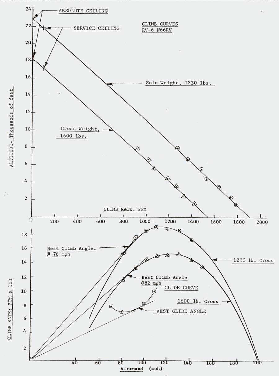
5.04 Climb Performance
PERFORMANCE GRAPHS TO BE ESTABLISHED
Best Climb angle 1230 lbs Gross 78 mph 68 Kts (Prov)
Best Climb angle 1600 lbs Gross 82 mph 71 Kts (Prov)
Best rate of climb 1230 lbs Gross 110mph 96 Kts (Prov)
Best rate of climb 1600 lbs Gross 120mph 105 Kts (Prov)
5.05 Gliding Range
PERFORMANCE GRAPHS TO BE ESTABLISHED
Best Glide angle 82 mph 71 Kts (Prov)
For every 1000 ft altitude the aircraft will travel approximately 1.75 miles at 764 ft. per min. sink rate. This is less than 5 deg glide angle. A stopped propeller will produce more drag than a windmilling one, so actual distance may be less.
5.06 Take off & Landing Performance
PERFORMANCE GRAPHS TO BE ESTABLISHED
Vans quoted figures:-
Take off distance 300/535 ft 91/163 Metres (Prov)
Landing distance 300/500 ft 91/152 Metres (Prov)5.07 Engine Performance
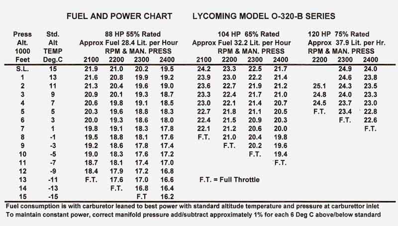
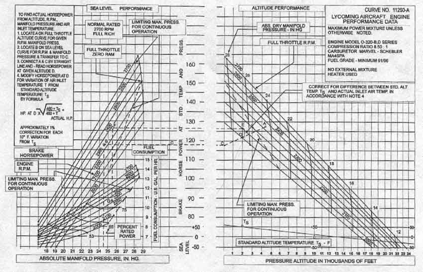
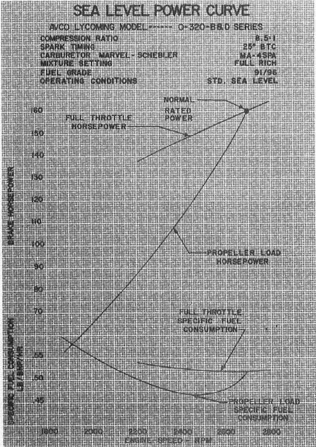
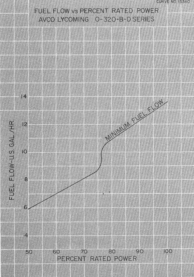
ENGINE PERFORMANCE GRAPHS AVAILABLE IN APPENDIX 2
Vans provisional figures are:-
Top speed 200 mph 174 Kts
Cruise 75% @ 8000 ft amsl 189 mph 164 Kts
Cruise 55% @ 8000 ft amsl 170 mph 148 KtsCombinations of RPM and Manifold Pressure are indicated in the Engine Performance Graphs. Over square settings are allowable within the limits defined in these charts (such as 2500 rpm and 28.4 ins Manifold pressure = 155 HP)
The table on the next page is the standard Fuel and Power Chart for the engine fitted. This is at Standard Pressure Altitude and Standard Temperature which should be adjusted for actual conditions.
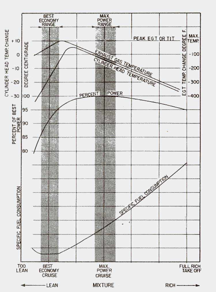
5.07.01 Engine Leaning
The following indicates the representative effect of leaning on Cylinder Head Temperature (CHT), Exhaust Gas Temperature (EGT), Engine Power and Specific Fuel Consumption at Constant Engine RPM and Manifold Pressure
6.1 General
So as to achieve the designed performance and flying characteristics the aircraft must be flown with the weight and centre of gravity (CG) within the approved operating range/envelope. It is the pilots responsibility to ensure the aircraft is loaded within its operating envelope before taking off.
An overloaded aircraft will not take off, climb or cruise as well as one properly loaded. Stall speed may be reduced.
If the CG is too far aft the aircraft may rotate prematurely during takeoff or tend to pitch up in the climb. Longitudinal stability will be reduced leading to inadvertent stall and even spins; spin recovery is difficult or impossible as CG moves aft of approved limits.
With a CG forward of limits it may be difficult to rotate for take off or land.
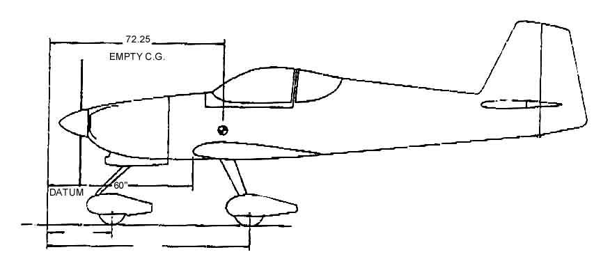
6.2 Weight and Balance Design Limits
Datum 60 ins forward of wing leading edge (LE)
Design CG Range:- 15%to 29% of wing chord
8.7 ins to 16.8 ins from LE
68.7 ins to 76.8 ins aft of datum6.3 Empty Weight Data (actual for aircraft)
ARM aft of datum
Nose wheel 27.10 ins
Main wheel right 81.73 ins
Main wheel left 81.65 ins
Fuel 70.00 ins
Pilot and passenger 87.4 ins
Baggage 117.0 ins
SEE APPENDIX 7 FOR DETAILED WEIGHT AND BALANCE SCHEDULE
SECTION 7
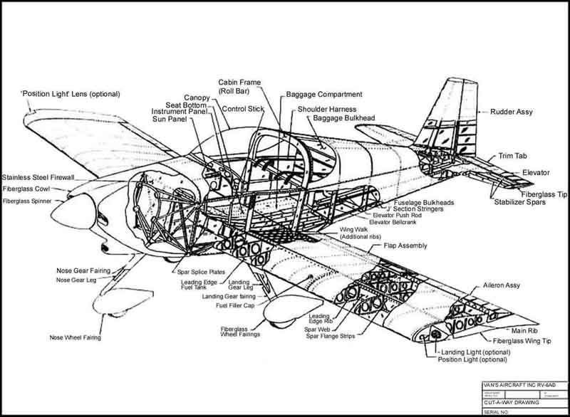
7.01 Airframe
The airframe is aluminium alloy construction except for steel components comprising :- engine mount, landing gear struts, main landing gear mounts, elevator bellcranks and other miscellaneous items. Fibreglass moulds are used for the tips of wings and tail surface as well as for cowls , wheel spats and empennage fairings.
The aircraft is conventially configured with a non laminar flow aerofoil (Wing NACA 2301.5, Tail NACA 0009), the effect of surface irregularities is relatively minor (compared to a laminar flow aerofoil).
7.02 Engine and Propeller
The aircraft is powered buy a Lycoming 0-320 B2B four cylinder, direct drive, horizontally opposed engine rated at 160 HP at 2700 rpm. The engine is fitted with a 60amp 14volt alternator, shielded ignition, vacuum pump, fuel pump and automotive type oiled carburettor air filter mounted in a ram air box underneath the engine which incorporates the carburettor hot air control system.
The exhaust system is all stainless with a crossover configuration and no mufflers. One heat shroud provides carburettor heat and another cabin heat as required being ducted to the centre section of the firewall.
The propeller is a MT MTV-18-C/180-119d three blade variable pitch propeller electronically controlled for constant speed. The system comprises a switchable automatic and manual cockpit control, which operates through a brush block, slip ring and rpm sensor on the engine. An electrical servo DC motor is supplied with power through the brush block and slip ring from the control unit. The servo-motor turns a spindle which moves a fork axially. Pitch change pins on the blades, extend into the fork, turn the blades within the desired pitch change. Mechanical stops limit the extent of pitch movement. In Manual mode the pitch is changed with a spring loaded toggle switch. In Automatic mode a pre-selector dial sets the constant speed in accordance with impulses from the rpm sensor in the brush block and slip ring assembly with an accuracy of +/- 30 rpm. A green light indicates a fine pitch setting in both Manual and Automatic modes. Normal operation is in Automatic mode. The system is fail safe because if the power supply fails the blades will stay in the last position, tending to move into the take off position (fine setting). Pitch change is 1 Deg. Per sec. and total movement approximately 20 Deg., slower than a hydraulic unit, requiring appropriate power management to avoid engine over-speed. As a guide for this aircraft a setting of 2,500 rpm for take off and landing is recommended under normal circumstances higher settings up to 2,700 rpm can be used though will require special attention to power settings to avoid engine overspeed.
The control unit performs a self-test when the master switch is switched on indicated by the yellow and green lights being on simultaneously for and second. This indicates satisfactory operation. A flashing yellow light at any time indicates a fault.
7.03 Landing gear
In tricycle configuration the landing gear legs are of spring steel (6150), to which a wooden preform has been fitted to the front of main legs to improve damping. The nose wheel is free castoring through Belville spring washers and uses Cleveland 44-70C wheels.
The main gear wheels, fitted with Cleveland 199-102 wheels and disc brakes
The braking system consists of toe brakes attached to the rudder pedals operating individual Cleveland brake cylinders to each of the main landing wheels, these share a common reservoir installed on the top left front face of the fire wall. A Cleveland dual parking brake valve, located on the inside of the fire wall above the pilot rudder pedals, is operated by a "T" handle on the centre control column. To operate the handbrake both toe brakes should be depressed and the handbrake pulled out into the on position (a twist may be necessary to release/engage the handle locking system). To release the handbrake push the "T" handle forward. As thermal expansion of the brake hydraulic fluid would damage the system seals use of the handbrake should be limited to short periods or to hold the aircraft briefly when chocks are not in place
Both brake pedals should have a similar feel and a firm resistance after ½" of pedal travel.
7.04 Flying controls
Flight control integrity is essential for safe flight. At installation or after maintenance it should be confirmed that ALL controls are connected, secured and safetied and that they all operate within the specified ranges smoothly and in the correct direction. Full travel should be confirmed prior to each flight. NO play should be permitted in the control hinges; sloppiness may induce flutter. Similarly trim tabs must be free of play.
Dual controls are provided. A bolt at the base of the passenger (right hand) control stick allows it to be removed without effecting the operation of the remaining controls. Elevator and Ailerons are operated through a system of adjustable push-rods. The rudder is operated through a cable system to the rudder pedals. An electrical trim system, operating through a "top hat switch" on the pilots control handle enables operation of elevator and Aileron trims both of which have a feedback position indicator located on the lower centre section of the instrument panel.
Flaps are operated electrically through a switch mounted above and to the right of the throttle.
The design specified control travel limits are: -
Surface Design Deg. Min Limits Deg. Actual as measured Deg
Aileron 30 up, 17 down 25up,15 down 30 up, 15 down
Elevator 30 up, 25 down 25 up, 20 down 28 up, 24.5 down
Rudder 35 right, 35 left 30 right, 30 left 30 right, 30 left
Flaps 40 down 40 down 43.8 full down
7.05 Engine Controls
Engine controls consist of a throttle control and mixture control mounted on a central console beneath the instrument panel.
The throttle is used to adjust engine RPM, forward being maximum and rearward for idle. The throttle cable control has a central plunger which operates a ratchet within the system which must be pushed in to enable the outer plunger to operate the throttle cable. Fine throttle adjustments can be achieved at any time within operating limits by rotating the outer plunger.
The mixture control is used to adjust the air to fuel ratio. Placing the control in the full lean rearward position shuts down the engine. The cable control knob is a central button lock type (normally locked) and is RED for easy identification.
The carburettor heat control is a Black cable control knob located beneath the throttle. Forward is cold, rearward in hot.
Note: Engine controls are configured for a "Forward to Go" position - i.e. Full throttle, Mixture Rich, Carburettor air Cold, Handbrake Off.
7.06 Fuel System
Fuel is stored in two 16 imperial gal. (72 litre) tanks secured to the leading edge structure with screws and plate-nuts. Fuel drains are fitted to the lowest point of each tank (and of the fuel system) and should be opened prior to the first flight of the day to check for sediment and water.
The fuel selector valve is located at the base of the central engine control column between the seats. A central button must be lifted to enable the handle to move into or out of the off position. In the central forward position the system will feed both tanks simultaneously into the system, this is a safety feature so fuel feed is never cut off when changing tanks, it is not intended that it would be used in this position during normal operations. The left tank has a fixed fuel feed tube whilst the right tank is fitted with a "flop tube" for inverted operation.
An auxiliary electric fuel pump is fitted in case of failure of the engine driven pump and is also used during take off and landing, and when changing fuel tanks in flight. The switch is located on the switch panel below the instrument panel on the left side, a Green LED located on the top left of the instrument panel indicates the switch is on.
A fuel gascolator is located on the left front lower fire wall. This is not the lowest point in the fuel system and is intended as a dirt trap only prior to fuel entering the engine driven fuel pump. The unit should be cleaned out and examined at 90 day intervals and/or service periods
Fuel quantity gauges are located on the right side of the instrument panel, and a fuel pressure gauge on the pilot (left) side.
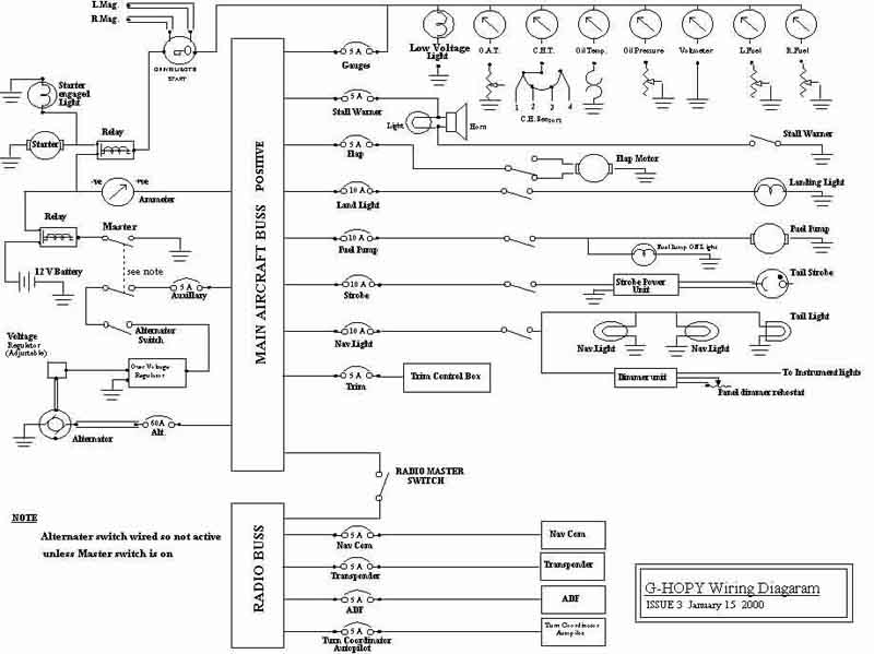
7.07 Electrical System
The electrical system includes a 14 volt 60 amp alternator, a 12 volt battery, and a solid state adjustable linear voltage regulator incorporating over voltage protection. In the event of an over voltage occurrence the AUX breaker will open - see section 3.03.09. The alternator switch is wired to be not on unless the master switch is in the on position.
Electrical switches are positioned in a sub panel on the left side below the instrument panel, with circuit breakers on the right lower instrument panel. A double pole switch, below the radios, isolates all radios, intercom and autopilot/turn coordinator. A dimmer rheostat on the switch panel controls radio and instrument lighting where fitted.
Electrical accessories include starter, electric fuel pump, stall warner horn and light, and gauges as listed in the equipment in - section 9.
7.08 Vacuum System
An engine driven dry vacuum pump operates the two vacuum instruments (Artificial Horizon and Direction Indicator) through a vacuum regulator, air being initially drawn through a fine filter. A shear drive protects the pump from damage, if the drive shears the gyros will become inoperative
A vacuum gauge fitted on the top left instrument panel provides information on system function. A decrease in pressure which has been constant over time may indicate a dirty filter, sticking regulator or system leak. A zero pressure might be a sheared pump, defective pump, collapsed line or faulty gauge. Any variation from the norm requires attention to prevent further damage and failure.
The vacuum regulator is to protect the gyros. It is normally set at 5.0+/- .1 ins Hg so as to operate all gyros at their rated rpm. At higher settings gyros will be damaged, at lower settings they will be unreliable. The regulator is mounted on the inside upper central section of the fire wall.
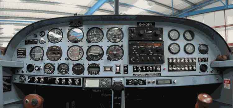
7.09 Instrument Panel
The instrument panel is fitted with instrumentation and controls as variously listed in this manual in section 9. Should a revised layout be required it should be noted that it is removable being retained by plate-nuts and screws.
7.10 Static air pressure system
The system supplies static pressure to the airspeed indicator, altimeter, vertical speed indicator and altitude encoder (which provides altitude information to the Transponder). The static pressure points are on the rear sides of the fuselage and are positioned to self drain. As part of the standard walk round checks the static vents should be inspected and confirmed as clean and open.
7.11 Heating and Ventilation
Cabin heat is provided via a heated muff attached to the exhaust system and fed with high pressure air from the left engine inlet cooling duct. Flow which enters through the centre of the bulkhead and is controlled with a ratchet cable control above the fuel valve and on the lowest section of the central control consul. Flow is off in the forward position. When in the off position air passing through the muff and ducts is dumped into the low pressure section of the cowl.Fresh air from ducts on the high pressure zone either side of the fuselage is fed into adjustable ducts either side of the instrument panel
7.12 Cabin and Baggage features
The seat back frames have adjustable positions at top and bottom to suit seating requirements. A full safety harness with crotch strap is provided which should be carefully fitted and adjusted prior to take off. In single person operations the passenger straps should be securely stowed. Straps should be checked regularly for damage
.A large baggage area with a maximum capacity of 100 lbs is behind the front seats, though weight and balance limitations will in practice be a constraint on that capacity.
7.13 Stall Warning
An approaching stall is indicated by the stall warning horn (located behind the instrument panel on the left) and by a red LED on the top left of the instrument panel. This is activated between 5 to 10 knots above stall speed. During preflight checks the stall warner lift detector (on outer section the left wing) should be lifted, with master switch on, to confirm horn and warning light operation.
SECTION 8
8.01 General
This section provides information on handling, service and maintenance of the aircraft.
The owner should stay in close contact with Vans Aircraft inc. so as to obtain the latest information pertinent to the aircraft including improvements or new equipment that may be of interest to the owner. It would also be useful to retain contact with other UK builders and users to exchange relevant information.
The owner should also obtain up to date service bulletins and Airworthiness Directives (ADs) related to installed equipment and particularly the Engine and Propeller and other proprietary items (Wheels, brakes, radio and navigation equipment etc.)
Information and directives may also be issued by the Popular Flying Association which could be advisory or mandatory. As failure to implement such a directive could contravene the issued Permit to Fly (as well a risking safety) it is essential the owner keep up to date on all such relevant information relating to the aircraft, and its installed systems equipment.
8.02 Ground Handling
Ground towing/ non taxi movement is best accomplished by use of the nose wheel steering bar. This fits into exposed socket cap bolts forming part of the nose wheel assembly.
When taxiing the aircraft ensure that the taxi path and propeller back blast areas are clear. In the first few feet of taxi apply the brakes to ensure effectiveness. Do not operate the engine at high rpm, taxi with care - a RV6 can take off at throttle settings no higher than those needed for engine run up and magneto checks.
When parking ensure aircraft is sufficiently protected from adverse weather and that it presents no danger to others (aircraft). Park the aircraft into wind if possible and moor securely with pitot cover on and flying surfaces secured.
8.03 Maintenance and Service
All work should be entered in the appropriate log book indicating:-
Date work was done
Description of work
Number of hours recorded on the aircraft at that time.
Name and signature of individual doing the work.
The following 25 hour check has been developed by the builder from a variety of relevant sources and based on his engineering judgement.
25 Hour check :-
Remove engine cowls for general inspection including the following:-
Wheels Check bearings for play.
Gascollator Empty bowl and replace noting any residue.
Oil hoses & filter Check for leaks and signs of loosening
Oil cooler General check of installation
Oil Check level and review top up frequency
Carb. Air inlet Check filter visually
Check carburettor heat functionality
Carburettor General exterior check including control cables.
Magnetos/Ignition General exterior inspection
Plug leads Inspect for condition
Fuel hoses. Check for leaks and signs of loosening
Fuel pump Check body joins for leaks
Primer system Check for integrity
Exhaust system: Check for blowing manifold gaskets
Check heat muffs (Carburettor and Cabin heat) & ducting
Check joints for wear/damage
Check mounting points
Check general integrity of system
Vacuum Check hoses
Engine mount Check for damage
Check mounting cotters (engine &bulkhead)
Check nosewheel frame elements for wear/damage.
Brake fluid Check level- note change since last filled/topped up.
Compartment wiring Check all wires for damage and security.
Cooling system Check all baffles for damage/wear/security
Check flexible sealing strips
Check blast tubes to Magnetos/Vacuum pump and Alternator
Propeller Check for nicks, scratches or corrosion and blade play.
Spinner Check spinner & backplate for cracks
General General review/inspection of Engine Compartment and propeller, spinner and its installation
Cowls Inspect for damage
Replace cowls and safety all locking pins etc.
Remove all wheel spats:
Tyres Check pressures Front 25 psi Mains 31 psi (cold)
Inspect tyres for wear and slip onn hub.
Brake system Inspect brake shoes, replace if appropriate.
Inspect hydraulic lines, joints and bleed points.
Check split pins and bolts for integrity.
Check nose wheel Belville washer (22lb at axle) torque.
General Check for wear/damage.
Spats Inspect for damage.
Replace wheel spats
General airframe and control surfaces review including, but not limited to:
Fiberglass components General inspection of fixing integrity
Fuel tanks Inspect for leaks and fixing integrity.
GENERALLY THE AIRCRAFT SHOULD BE MAINTAINED IN ACCORDANCE WITH
CAP 442
LIGHT AIRCRAFT MAINTENANCE SCHEDULE FIXED WING
CAA/LAMS/A/1999
NOTE:- A detailed 50 hour and Annual maintenance schedule is given in appendix 4. This is based on the above LAMS schedule as adjusted for G-HOPY and Textron Lycoming Operator’s Manual.
EQUIPMENT LISTING
9.01 Engine, accessories & Instruments
Engine Lycoming O-320-B2B, the standard engine specification has been changed to include a full flow cartridge oil filter and has been fitted with a different Sump to accommodate a forward position carburettor as required for the RV 6A nose wheel configuration. This effectively changes the engine to a O-320-B2A specification. Engine serial number is L-4741-39
The following engine instruments are fitted:-
ITEM DESCRIPTION SERIAL NUMBER
Tachometer Stuart Warner P511 AZC GI/21810
CHT/EGT Westach 2 DA1 2091
Vacuum UMA inc PIN 3-200 A9355
Fuel gauges (2) ISSPRO IER8690 None
Oil pressure/Temp Racetec PT1014BL7 None
Manifold perssure Vans VMP 35E MP SND None
Fuel pressure UMA 3-331-23 A2325
Fuel Flow Matronics Fuel Scan LT OB1E3F479.02 Propeller
ITEM DESCRIPTION SERIAL NUMBER
Propeller MTV-18-C/180-119d 02056
Spinner P-469-2
Control Unit P-120-U/2700 W01-0040 db9.03 Radio equipment
ITEM DESCRIPTION SERIAL NUMBER
Nav/Com NARCO 12D TSA No B832853323
DME NARCO IDME 891 10712
Transponder NARCO AT 150 TSO 14338
Altitude encoder NARCO AR 850 60510
ADF KING KR 85 TSO 26048
ADF indicator KING KI 225 25113
Intercom Sintronics SPA 400 TSO 60536449.04 Flight Instruments
ITEM DESCRIPTION SERIAL NUMBER
Altimeter Model BG 3A 2031
Vertical Speed Ind. Model BC 2A 0097
Attitude Gyro Sigma-tek 5000B-42 T73773M
Direction Gyro Sigmatek 4000B-30 T54887K
Autopilot Navaid Devices AP1 001102
OAT Westach
Magnetic Compass Unknown make
ASI United Part No 8025 153292
Angle of Attack PSS AOA Sport 1299V3 260
ITEM DESCRIPTION SERIAL NUMBER
Voltmeter ISSPRO IER8690 None
Ammeter ISSPRO IER86666 None
Battery Sonnenschein Dryfit A500/30.0 G6
Alternator Nippon Denso ND47 60 Amp
Voltage Regulator LR 3C-14 042310719.06 Other Equipment
Fanbelt Automotive Belt QH Part number QBA 950
Nose Tyre Lamb 11x4.00-5
Main Tyres Aerotrader 5.00-5
9.07 Supplier list
Vans Aircraft
14401 N.E. Keil Road
Aurora
Oregon 97002
Tel: 001 503 678 6545
Fax: 001 503 678 6560
Lycoming Agent:
CSE Aviation
Oxford Airport
Kidlington
Oxford
OX5 1RA
Parts Supplier
Light Aero Spares
Shebbear
Beaworthy
Devon
Fax 01409 281680
Parts Supplier
Sport Plane
PO Box 34
Wallingford
OX10 0LQ
Fax: 01865 379123
Tel: 01865 841234
Tel/Fax: 01491 838292
Aircraft Hoses
RF Saywell Ltd
Brookside Avenue
Rustington
Little Hampton
West Sussex
BN16 3LF
Tel: 01903 858700
Fax: 01909 858101/2
Oil Analysis
Spectro Oil Anaysis
Fairoaks Airport
Tel: 01276 857854
Tools and Materials
Cleveland Tool & Material
1804 First Street
Boon
IA 50036
Tel: 001 515 432 6794
Fax 001 515 432 7804
Propeller Supplier
MT-Propeller Entwicklung GmbH
P.O. Box 0720
D-94307 Straubing
Germany
Tel: 0049 (0)9429/94090
E-Mail: sales@mt-propeller.com
Fuel Flow
Matronics
PO Box 347
Livermore
CA 94551-0347
Tel: 925 606 1001
E-Mail: support@matronics.com
Angle of Attack indicator
Proprietory Software Systems Inc.
950 Iris Circle
Excelsior MN 55331
Tel:952 474 4254
E-mail: PSS@Angle-of Attack.com
APPENDIX CONTENTS
1 Electrical Diagrams
2 Performance curves
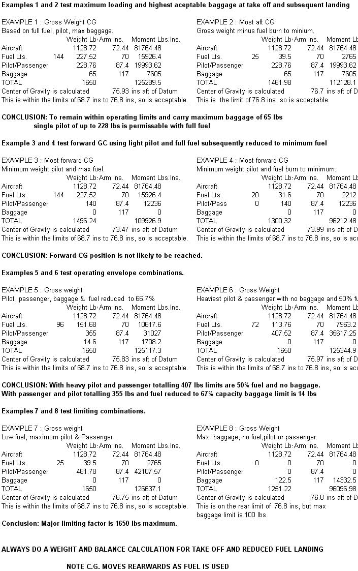
3 Weight & Balance
4 Maintenance
PERFORMANCE CURVES
APPENDIX 3
WEIGHT & BALANCE
 (includes 8qts of oil,
no fuel)
(includes 8qts of oil,
no fuel)
The following maintenance schedule is based on CAP 411 LIGHT AIRCRAFT MAINTENANCE SCHEDULE (FIXED WING) CAA/LAMS/A/1999 Issue 1 and Textron Lycoming Operators Manual to Revision April 1998
Maintenance Cycle:
50 Hours check At 50 Hours or 6 Months whichever sooner
100 Hour check At 100 Hours. Comprising 50 Hours & 100 Hour items
150 Hour check Comprising 50, 100 & 150 hour check items at 150
Flying hours
Annual check 50, 100, 150 hr. & annual check items not
exceeding 12 months
Permitted variation:
50, 100 & 150 Hour check 10%
6 months 1 Month
Annual None
Check power plant, liquid, air and gas systems for leaks
during and following ground run.
Check instruments, systems and services. Radio for electromagnetic interference.
Following ground run, ensure all cowlings, access panels are secure.
Ensure Engine, Airframe and Propeller logbooks have been correctly filled in, certified and are up to date. (All flights and work carried out must be entered and signed up as required)
Ensure all mandatory placards are installed and legible.
Check all mandatory requirements (modifications, inspections and other directives) have been complied with.
Review maintenance schedule to ensure all maintenance needs are being met to continue safe operation. Account to be taken of maintenance history, operating environment and utilization.
Structural/Zonal
50 Hrs
Inspect external surface of fuselage, mainplanes, empennage, cowlings, nacelles, flaps and control surfaces.
Check and inspect sliding canopy fit, operation and condition including satisfactory operation of latching and locking mechanism.
Check protective treatments, drain holes free from obstruction, access panels secure
150 Hrs
Remove all inspection panels, rear cabin bulkhead, internal flap mechanism inspection panels and floor panels over control stick mechanism. Remove faring over empennage.
Inspect internal structure of fuselage, wing and empenage revealed by removal of above items.
Inspect internal corrosion protection, drain holes and paths.
Minimum 10 years (earlier if required)
Reweigh and check weight and balance schedule.
50 Hrs
Remove wheel spats and inspect for damage.
Inspect landing gear legs and fixed fairings for damage and integrity
Check brake system for leaks.
Inspect brake pads and discs for condition and wear
Check brake fluid reservoir (Fill as required)
Check tyre condition and tyre pressures (Main 30 psi Nose wheel 25 psi and not greater than 27 psi)
Check nose wheel assembly belville washer break torque (22 lbs at axle point)
Replace wheel spats.
150 hrs
Inspect structural members and attachment fittings.
Inspect and check all brake hydraulic pipes, flexible hoses, connections, master cylinders and parking brake system for correct operation.
Inspect wheels for alignment.
Support the weight off the wheels and check wheel bearings for play. Check landing gear mounting bolts.
Inspect wheels for cracks, corrosion and broken bolts.
If required lubricate wheel bearings. Lubricate nose wheel swivel system.
50 Hrs
Check flying controls for full and free movement and in the correct sense.
Check correct operation of trim mechanisms and that indicators agree with surface movement.
150 Hrs
Inspect all control surface hinges, hinge bolts, brackets, push-pull rods, bellcranks, stops, control horns and balance weights. Check associated turnbuckles/locking systems.
Check control neutrals and travel.
Inspect rudder control cable, fairleads and cable guides.
Inspect rudder pedals and pedal mechanism.
Check flap operation, mechanism, and actuating system.
Check and inspect aileron and rudder trim for correct operation and security.
Annual
Inspection and operation of Electric flap actuating system
50 hrs
Inspect Vacuum system
Inspect Pitot/staticsystem vents. Pitot head, Drains clear. Pitot head correctly aligned
150 Hrs
Inspect tanks, filler caps, valves, pipelines, and hoses.
50 hrs
Check first aid kit complete and within expiry date
Check seat belts/harnesses for satisfactory condition, locking and release.
Check seat belt/harness mounting points and brackets
Check expiry date of carbon dioxide warning disc.
Check fire extinguisher for leakage/discharge.
150 Hrs
Operational check and inspect Cabin air system
Check cabin heating system controls, hoses and ducts
Check and inspect cabin heat exchanger for signs of exhaust gas leakage.
Check Fire extinguisher by pressure
50 Hrs
Lubricate aircraft as appropriate (all rod end and hinges)
50 hrs
Engine cowls, clean and inspect for damage (cracks, distortion loose or missing fasteners).
Operational check of engine controls for full and free movement – throttle, mixture, carburettor heat system including air door and box.
Inspect spark plug cable leads/ ignition harness and ceramics for damage, corrosion and deposits. If fouling spark plugs apparent, rotate bottom plugs into top position.
Check ignition harness for security of mounting clamps and ensure connections are tight at spark plug and magneto connections.
Check cylinders for evidence of excessive heat (burnt paint on cylinder). This condition is indicative of internal damage to the cylinder and cause MUST be determined.
Inspect rocker box covers for evidence of oil leaks. If found replace gasket, torque cover screws 50 inch-pounds.
Cooling system Check cowling and baffles for damage and secure anchorage.
Inspect air intake seals, ducting and clamps.
Inspect vent lines for evidence of fuel or oil seepage
Inspect all wiring connections to the engine and accessories.
100 Hours
Check all wiring connected to the engine or accessories. Any shielded cables that are damaged should be replaced. Replace clamps or loose wires and check terminals for security and cleanliness.
Engine Accessories Check for secure mounting and tight connections
Cylinders Check visually for cracked or broken fins.
Engine Mounts Check mounting bolts and bushings for security and excessive wear. Replace excessively worn bushings.
Carry out a cylinder compression check at a standard 80 psi, record in logbook and note change compared to previous checks. A pressure loss in excess of 25% of the 80 psi (a reading of 60/80) is the recommended minimum allowable
150 Hrs
Inspect accessory housings, cylinder assemblies, bulkhead/firewall and sealing, cooling baffles/seals, cowlings, items in engine bay for mutual interference.
Inspect vacuum pump and lines
Inspect throttle, carburetor heat, mixture and cabin heat controls for security, travel and operating conditions
Inspect breather tube for obstructions and security
Inspect crankcase for cracks, leaks and security of seam bolts.
Clean engine as required (care not to contaminate vacuum pump with cleaning fluid).
400 Hours
Remove rocker box covers. Check for freedom of valve rockers when valves are closed. Look for evidence of abnormal wear or broken parts in the area of the valve tips, valve keeper, springs and spring seat. Any damage requires removal (including piston and connecting rod assembly) and inspection for further damage.
1000 Hours
CONSIDER overhaul or replace vacuum pump
CONSIDER replacement of flexible oil lines (earlier if required)
CONSIDER overhaul or replace fuel pump
2000 Hours
CONSIDER engine overhaul or replacement
100 Hours
Remove spark plugs; test, clean and regap. Replace if necessary.
Electronic ignition, Hall Effect sensor. Remove cover plate and inspect bearing and seal wear.
Magnetos – Check breaker points for pitting and gap. Check for excessive oil in the breaker compartment, if found wipe dry. Breaker point felt to be lubricated. Check magneto to engine timing.
150 Hrs
Inspect Magneto and Electronic ignition harness leads
Carry out high-tension leakage and continuity test.
Inspect magneto points for condition and correct clearance.
Inspect Magneto for oil leakage
Inspect breaker felts for proper cam lubrication.
Check Magneto to Engine timing
Inspect condition of spark plugs (clean and adjust gap as required). If fouling of plugs is apparent rotate bottom to upper plugs.
500 Hours
Inspect distributor block for cracks, burnt areas or corrosion and height of contact springs.
Or 3 years. Lightspeed recommend replacement of Electronic ignition leads. Note type is important – do not use shielded aircraft leads or high resistance automotive leads1000 Hours. CONSIDER overhaul or replace magneto
50 hrs
Inspect air filter, intake and induction system.
Remove and clean air filter.
Exhaust system
50 hrs
Check attaching flanges at exhaust ports on cylinder.
Examine exhaust manifolds for general condition.
150 Hrs
Inspect exhaust stacks, connections and gaskets. (Replace gaskets as required).
Inspect mufflers, cabin heat exchanger and tubes.
50 hrs
Drain oil sump.
Remove oil suction and pressure screens and check for presence of metal particles which are indicative of internal engine damage.
Change full flow oil filter, split used filter and inspect.
Clean oil screens
Inspect oil lines and fittings for leaks, security or damage
Refill engine with oil (see manual section 1.5)
150 Hrs
Clean and inspect oil radiator cooling fins
Inspect Sump, Oil hoses pipes and vent.
Inspect oil sender connections and pipe for leaks and security.
500 Hours
Remove and flush oil radiator
90 days
Remove and clean fuel filter bowl and screen.
50 hrs
Check primer lines for leaks and security
Drain samples from drain points and check for water, foreign matter and correct colour.
Drain carburettor and clean inlet line fuel strainer.
Check tank vents unobstructed.
Inspect fuel system/lines and tank for leaks.
Remove and clean fuel filter bowl and screen.
150 hrs
Inspect condition of flexible fuel lines
Check operation of fuel selector valve.
Inspect fuel gauges for damage and operation.
Inspect security of all fuel lines
Inspect fuel boost pump
1000 Hours
CONSIDER replace flexible fuel lines (earlier if required)
50 hrs
Inspect spinner and back plate, and spinner attachment screws.
Inspect propeller blade for damage.
Cycle and check electrical pitch control operation.
150 hrs
Remove spinner, inspect propeller and spinner assembly for security and damage or wear.
Inspect propeller mounting bolts and safety (check torque if safety is broken).
Inspect Propeller motor drive brushes for condition and wear
1000 Hours
CONSIDER propeller overhaul or replacement
1800 Hours (72 Months)
Propeller overhaul. Mandatory
50 Hrs
Check and inspect battery installation, vents and drains.
Check operation of all electrical circuits.
Inspect Alternator/generator drive belt tension and condition.
Check all controls and switches labelled correctly
150 hrs
Inspect components, wiring, terminals and connectors.
Operational check of all warning circuits
Check correct type and rating of fuses and circuit breakers.
Check lamps and lights
Check starter brushes and alternator belts tension/drive.
Inspect condition of alternator and starter (and mounting integrity)
Ensure voltage regulator operating correctly (pushing test button with engine running and alternator on should cause 5A AUX breaker to open in 1 Sec.)
Annual
Consider battery capacity check
50 hrs
Inspect aerials, insulators, instruments and displays.
Check placards and markings legible
Carry out VHF ground function check
Inspect cables and terminals.
Annual
HF communication test the function of the system including Audio panel
ADF carry out ground function test for accuracy and audio indent.
The following checks (as legal requirements for CAA certified aircraft) should be considered. As a minimum a flight check should be completed to confirm satisfactory operation: -
ILS Localiser and glide slope carry out check with Field Test Set, including flag warning. Check centre lines accuracy, sense and course width. Check audio.
VOR carry out check with Field Test Set, including flag warning, omni-radial resolving and radio-magnetic accuracy at 90 deg intervals. Check sense and course width.
DME - carry out check with Field Test Set, including range accuracy.
ATC Transponder - carry out check with Field Test Set . Check – frequency tolerance and side-lobe suppression. Check – Mode "C"
50 hrs
Inspect instruments for damage, and legibility of markings and associated placards.
Check instrument readings are consistent with ambient conditions; operation, as far as possible on engine ground run. Perform manual override and disengagement checks.
Check stall warning device operation.
Check last compass swing date (and any other instrument calibration dates) and assess if renewal required.
150 hrs
Inspect instruments: panel; mounts; pipes; hoses; electrical wiring.
Check pitot/static system for leaks
Inspect instrument vacuum filter (consider change at 200 hours)
50 hrs
Check wing leveler/autopilot operation in accordance with manufacturer recommendations
150 hrs
Inspect and check wing leveler/autopilot connections, servo installation and associated control links.
To operate the aircraft a Flight Release Certificate (FRC) issued by an approved PFA inspector (or suitably licensed CAA engineer) must be in force and valid. The FRC is invalidated when the airworthy condition of the aircraft is changed (damage sustained, improper storage, component failure etc) or work is carried out not within the scope of the Pilot Maintenance (PFA Information Sheet 1 Issue 1 1991)
In addition to FRC a valid Permit to Fly must be in force.
Aircraft insurance is not a legal requirement. It is however PFA policy for aircraft to have adequate third party and passenger insurance.
7.00 Pilot Maintenance not requiring a new Flight Release Certificate
Pilot maintenance (as specified in PFA information sheet 1 issue 1 1991) relevant to RV6A G-HOPY, not requiring re issue of a FRC is as follows:-
Changing engine oil (including removal, cleaning/replacement, refitting oil filter).
TORQUE SETTINGS
Exhaust Stack (High Country Recommendation) 100/140 in lbs
Lycoming & Lightspeed Recommendation:-
¼ in. 8 ft lbs 96 in lbs
5/16 in 17 ft lbs 204 in lbs
Plugs (Magneto driven) 30/35 ft lbs
Plugs (Electronic driven) 15 ft lbs
Brass Spark plug reducer 25 ft. lbs
Engine Mount bolts 40 in lbs
Rocker Cover Screws 50 in lbs
General Torque settings STEEL (fine threads):-
AN3 (3/16 in) 20-25 in lbs
AN4 (1/4 in) 50-60 in lbs
AN5 (5/16 in) 100-140 in lbs
AN6 (3/8 in) 160-190 in lbs
General Torque settings ALUMINIUM ALLOY (coarse threads lower setting):-
3/16 in 5-6 in lbs
¼ in 8-10 in lbs
5/16 in 19 - 22 in lbs
MAINTENANCE DATA
Tyre Pressures: Main 30/33 psi Nose 22/25 psi (Not greater than 25 psi)
Spark plugs: -
Magneto ignition. Champion REM 40 E Gap: .016 to .021 Ins.
Electronic Ignition
Denso W27 or Bosch W270-310 (or 1-3) or NGK 9-10 ins. Gap: .032 to .040